Pulse Width Modulation (PWM) is a technique used to encode a message into a pulsing signal. The technique consists of modulating the width of a fixed-frequency rectangular pulse wave in direct proportion to a small control signal. The resulting PWM signal can be used to control the power delivered to a load, such as a motor or a light bulb, by adjusting the duty cycle of the waveform. PWM is used in a wide range of applications, including motor control, lighting control, and power regulation.
PWM has some advantages over traditional analog control techniques, such as greater control resolution, and reduced component wear. It also has some disadvantages, such as the need for additional hardware to filter the PWM signal and convert it back to an analog signal, and the generation of audible noise from the PWM signal.
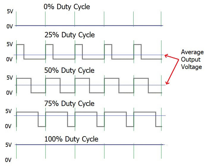
In PWM, the microcontroller sends a series of pulses to the analog circuit. The duty cycle of the pulses, or the ratio of the pulse width to the total period, determines the average value of the signal. For example, if the pulse width is 50% of the total period, the average value of the signal is also 50%. By adjusting the duty cycle of the pulses, the microcontroller can control the average value of the signal, and thus control the power delivered to the load.
PWM can be used to control DC motors, since the average voltage applied to the motor is proportional to its speed.