Here the circuit of the “One Wire Hackbrett”:
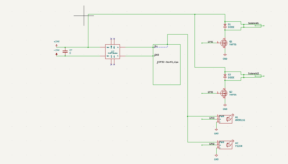
After applying the 24V power supply to the circuit, the signal splits into two directions. The first one goes directly to the Solenoids that are driven with PWM signals through the microcontroller:
- PWM stands for Pulse Width Modulation. It is a technique used to control the amount of power delivered to a load by controlling the duration of a series of pulses. The duty cycle of a PWM signal is the proportion of time that the signal is in the “on” state (high) compared to the total period of the signal. It is typically expressed as a percentage. For example, if a PWM signal has a duty cycle of 50%, it means that the signal is in the “on” state 50% of the time and in the “off” state 50% of the time. The relation between the duty cycle and the power delivered to the load is that a higher duty cycle corresponds to more power delivered to the load. To avoid burning the magnet,
The second goes across the DC/DC Stepdown converter that transforms the power into 5V since the ESP32 microcontroller produces only 3.3V (not enough to drive efficiently the motors).